High voltage switching power supplies Circuit Diagram
High voltage switching power supplies Circuit Diagram If this type of switching arrangement is acceptable, then the low-side switch is usually the cheapest way to achieve load switching. BJT Low-Side Switch A BJT can be used as a load switch and come in two flavors: NPN and PNP. For low-side switching, NPN transistors are used, and for high-side switching a PNP is used. When we need to switch moderate to high levels of power, one of the best methods we can use is a transistor with an open-collector output. In this setup, we connect the emitter terminal of the transistor directly to ground. Electronics Tutorial about the Transistor as a Switch and using the Transistor as a Switch to operate relays, motors, lamps and other such loads

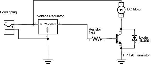
Figure 7 shows the basic circuit for using a transistor to control a high-current load. You connect a DC power source to one terminal of the load, then connect the second terminal of the load to the collector of the transistor (or drain, for a MOSFET) of the transistor.

Low side vs. High side transistor switch Circuit Diagram
Here's how to set up both the BJT and the MOSFET transistor as a switch so you can easily control things like motors, lamps, and more.
These pins are meant to send control signals, not to act as power supplies. The most common way to control another direct current device from a microcontroller is to use a transistor. Transistors allow you to control the flow of a high-current circuit from a low-current source. Video: Transistor Schematics Video: Meet the motors However, if you are delivering power to an entire circuit or a voltage-sensitive device, then you want to use a high-side switch. By the way, there are off-the-shelf components called " load switches." These ICs have a P-Channel MOSFET as the switching transistor with a built-in driver for that P-Channel.
How to Use Transistor as a Switch with Example Circuits Circuit Diagram
For the transistor to operate as a switch, a principle of the small base current controlling the large collector load current is used. If you want to control large currents, use the Darlington transistor as a switch
